Author Archives: Richard

Microwave Install

I had replaced the microwave oven that came with the house 15-18 years ago, and late last year the replacement failed.  It was the over-the-range type and had installed fairly easily, but we discovered over the years that the microwave was too close to the range top, making it difficult to stir tall pots sitting on the back burners.

IMG_20180402_133059

This view shows an 18 quart pot and lid on the big back burner under the old microwave.  It is not a pot we use very frequently, but even stirring pasta in an eight quart pot on the same burner proved somewhat problematic.  To make matters worse, the replacement microwave oven we wanted was even taller and wouldn’t fit in the space between the shelf and the top of the tiles of the backsplash.  The solution was to install the new microwave higher, which involved tearing into the shelf above the range and installing a new shelf.

IMG_20180402_133006.jpg

After removing the old microwave and trim piece from the cabinet shelf, here is what it looked like:

IMG_20180402_143459

Over-the-range microwave ovens are supported by a bracket mounted on the wall behind it, but much of the oven’s weight is borne by bolts through the shelf above the microwave.  It isn’t clear in the pictures, but the old shelf shown here is supported very well in rabbet joints or slots in the vertical part of the cabinets on either side of it.  The solid wood trim piece (not shown) adds rigidity to the plywood shelf, helping to minimize sagging of the shelf when the microwave is bolted to it.

IMG_20180402_151846

I used an electric jig saw to cut through the shelf and tore it out in two pieces.

IMG_20180530_121744

From a piece of oak plywood purchased at a home center store, I cut out a shelf using a circular saw such that it would fit snugly in the space between the two cabinets.  The plan was to mount the new shelf 4.0 inches higher than the original shelf.  Cutting the shelf piece involved careful measuring, marking, and sawing.  Having a good quality circular saw really helped.

I used the template that came with the new microwave oven to modify the shelf before installing it.  I stained and finished the wood with leftover supplies from when we had the kitchen cabinets refinished.

IMG_20180528_064453

The holes in the shelf didn’t seem to quite line up with the holes in the new oven, so I filed one of them into a slot or slightly elongated hole.  I used a rat-tail file to do this.

Prior to tearing out the original shelf, I used a scribe to mark a line 4.0 inches above the old shelf.  I extended this along the thin plywood back of the cabinet and cut out the excess part of the back of the cabinet with a sharp knife.

IMG_20180528_064519

I slid the new shelf in and aligned it with the line I had scratched with the scribe, and supported the shelf with temporary metal supports that were originally manufactured to hold screens into window frames.  I also marked where the shelf would go with pencil and masking tape.  In the photos you can make out where later I drew the center line of the shelf and marked about every inch where holes for supports would go.

IMG_20180528_064535

I drilled nine pilot holes from where the shelf would be into the cabinets on either side.  This way when I would back-drill the pilot holes from inside the cabinets, they would be centered in the shelf even if I didn’t drill these pilot holes particularly level.

Here are several photos showing how the pilot holes looked before sliding the shelf back into place.  They show the nine pilot holes on each side, from both sides of the cabinet walls:

IMG_20180528_115631

Next I slid the shelf into place and lined it up as perfectly as I could.

IMG_20180528_121511

IMG_20180528_121533

Then, I back-drilled four pilot holes into the shelf for nails that would hold the shelf in place for the next step: attaching it between the two cabinets.

IMG_20180528_122643

IMG_20180528_122635

With the shelf pinned by nails, all that remained was to fasten it more permanently.  I had thought I would used wood screws, but realized screws would act as wedges that could split the plywood shelf.  Some experimentation with scrap material bore this out, and wood dowels seemed more like the way to go.  I got some 5/16″  wood dowels and following advice I read on the internet, also employed a clamp to hold the plywood together the best that I could while drilling the shelf and installing the dowels.  I didn’t have a proper wood clamp, so I did the best that I could.  The dowels that were to support the most weight were installed where the clamp was most effective, close to the front of the shelf.

IMG_20180528_123125

I employed a makeshift depth gauge to back-drill the pilot holes to the correct depth for the dowels …

IMG_20180528_123654

… and did the same thing for the 5/16″ drilling of holes for the dowels.  Here is what it looked like before installing the dowels on the left hand side.

IMG_20180528_130536

I made a nozzle for my glue bottle using pieces from old caulking tubes.  This helped greatly in loading up the drill holes with wood glue.

IMG_20180528_160113

IMG_20180528_132627

After installing seven dowels on one side, I could pull out the two nails and install two more dowels.

IMG_20180528_132657

After removing the clamp, I found a bit of a glue mess, but that was easy to clean up.

IMG_20180528_133554

The dowels on the right hand side went in quickly and easily.  I used a blend/fill pencil to cover up the imperfections.

IMG_20180530_084453

I followed the directions that came with the new microwave oven to install the wall bracket.  I added a support under the shelf at the back, but didn’t figure that really helped much.

IMG_20180529_231931

You can see the trim piece that I glued and nailed to the front of the shelf.  As mentioned earlier, this adds rigidity to minimize the shelf sagging under the weight of the microwave.  With help, I installed the new oven.  It was quite heavy, but went in easily.

IMG_20180530_110601

I had set up the microwave oven’s vent fan to exhaust up so that exhaust air could vent through a hood boot to the existing vent on the roof.  The vent pipe was not centered, and the spacing was such that standard parts would not allow connecting the oven’s vent to the vent pipe.

IMG_20180713_133612

I designed a hood boot and a flat piece to finish off the hole through the top of the cabinet.  The rectangular dimensions of the hood boot are per the instructions that came with the microwave, but I came up with the offset and height through careful measuring.  Here are the designs of the flat ring and the microwave hood boot.  A local custom sheet metal company fabricated the two parts.

Fortunately the vent pipe would move up about an inch, making it possible to set the hood boot  without too much trouble.  I used metal tape to connect the boot to the stack, and screws to install the flat ring.  Here is how it turned out.

IMG_20180907_142628

To finish the project, something has to be done about cabinet doors since the old ones are too tall now.  Also something has to be done at the backsplash because now there is a gap between the tile and the bottom of the new microwave oven.  (The bottom of the new microwave is a little over three inches higher than the old microwave.)  We are still trying to decide what to do on these last two items, but in the meantime, we have a microwave oven that works, and a hood vent that works.


Bats!

The sugar water in a small glass hummingbird feeder disappears every night.  Nothing is left in the morning except strange smudgy marks on the lid and sometimes a small green wasp-like fly or two, either stuck inside or scouring the film of sugar on the outside of the feeder.  There is one in the image below.

IMG_20180819_075642

I set up a trail camera a few nights ago and got videos of one night’s visitors.  The camera’s flash must have startled them, because they didn’t come back after midnight, and there was still sugar water in the morning.

Here is a link to the most active video I got: https://youtu.be/tOkp2TfE33A

The next night I set the camera up for still shots and got 2x images 124 times.  The pictures didn’t come out very clear, but you can tell something is there, coming in for a landing and clinging to the feeder in these two images:

IMAG0055

IMAG0056


They were there all night.  The last of the bat images was right before 5:00 a.m.  When it started getting light, birds were checking it out.

IMAG0243

IMAG0244

Repaired EZ Cart

Eve asked about the cart shown in the post Dirt, Rocks, Stairs.  It had been used a lot, and the project of making the stairs did it in.  The plastic broke because of too much weight being put in the cart.  I had rigged it to work a time or two and it was fine for light loads, but I imagined I could fix it, and after getting the question, I got around to doing something about it.

I bought some slotted angle, 1-1/4 inch, 18 gauge, zinc plated.  It is not too heavy duty, but stronger than the plastic.  I also got 1/2 inch machine screws, 1/4-20, matching nuts of the locking type with Nylon to lock them in place, and washers to go under the nuts so they wouldn’t break through the plastic when tightened down.

The plastic was split right where the support attached.  I attached the angle on the left side of the break first, drilling 3/8″ holes to match the holes in the angle.  With the angle securely attached on the left, I used a long clamp to pull the split back together.  Then I attached the angle on the right side as before.

Once the gap formed by the break was closed, I reattached the support, adding washers against the plastic on both the inside and the outside:

The brand of cart is EZ Cart by Republic.  Looking on-line, it is no longer manufactured.  Here are the markings:

Tagged , ,

washing dishes, a memory

I found out recently that Steve Bailey died in 2013.  There were some pictures in the in-memory section of the reunion builder website for my high school class, and a writeup about the man I knew as a high school kid.  Steve had worked in food service – maybe all his career – and it seemed he had done well as a chef at some prestigious restaurants.

Naturally I am not aware of this when he calls me one summer day before our junior year of high school and asks me to cover for him at his job washing dishes at a local lunch and dinner place I drive by all the time but at the same time have no plans to visit.  I want to say no, out of a tendency to avoid new experiences, especially ones that mean hard work.  But Steve parries all of my excuses with pleas that he must find a replacement, and I show mercy, not because I am a merciful person, but because I can’t figure any way out of it.

Every summer in the small Oklahoma town of Bartlesville seems to bring at least one case of poison ivy, and the summer of 1968 is no exception.  I have a raging dose of it when I show up for the first day of a week of labor.  The restaurant is dark and cool compared to the cicada-buzzed humidity just outside the door.  I walk cautiously into the dining area as my eyes adjust, and I meet the man who runs the place, one Al Jay Kester.  Al Jay is in his prime, 28 and chubby, either by nature or lifestyle.  He cooks me a sandwich at some point, a grilled cheese and ham sandwich that he opens up to insert crisp iceberg lettuce and Miracle Whip before serving it to me.

Later in the year, on a fine October day, Al Jay will kill a woodchuck while hunting along the banks of the Caney River.  His picture will be in the local paper, the Examiner Enterprise, on Halloween Day 1968.  He will not yet be 29 years old, and he will be just beaming with pride displaying his kill.  I will tear out and save the small newspaper article and goof with my friend Steve about how the caption makes it unclear whether the woodchuck or Al Jay was climbing a tree when he shot it.

Al Jay leads me out of the dining room and into the kitchen and then further into another area that is my work place, the dish washing station.  Heat is bad news for the sufferer of poison ivy.  It makes the rash bubble and blister.  I have it on my forearms and torso, but it is really bad on my legs.  What is worse than the general heat of the kitchen, the water in the metal sink for washing dishes is heated by an open gas burner at about knee height and right under the sink.

Al Jay will give me no instruction on operating the sink.  For all I know, the burner is to remain on the entire time I am in the restaurant.  The water will be so hot that I will be scalded multiple times in the week ahead, especially when I reach to the bottom of the sink to fish around for the stainless ware, plates, and kitchen utensils.  The heat from the burner will turn my usual bad case of poison ivy into my worst experience of this allergy.

After showing me my work place, Al Jay takes me to where a small primate, maybe a rhesus monkey, lives behind the restaurant, tethered by a chain to a stake in the ground.  He tosses some bits of food to the monkey.

When I learned about Steve Bailey dying of cancer, I thought about that restaurant where he worked and about some of the old times, and old places in and around Bartlesville, about another restaurant called Marie’s that was near the go kart track, and not far from there the road that used to go over the memorial bridge over the Caney, right before you would get to Floyd’s gas station where we always stopped to fill up.  I thought about driving around and knowing all the back roads, to places like Hudson Lake and Hula Lake, and places in Osage County I didn’t know, but that I knew how to get to.  I thought about Circle Mountain, and going there for a bonfire with my brother and his friends and girlfriend Roni back from college, drinking Boone’s Farm into the night, and remembered not remembering them helping me to bed, back home at my folks’ house.

From what I can tell, Al Jay is still in the area.  There is a webpage entry from February about him on a Bartlesville website, and he was preparing to write his memoir at the time, according to the entry.  I wonder if Al Jay remembers things the way I do, whether he remembers about Floyd’s, about the lakes and Circle Mountain, and about cicadas and the restaurant where Steve used to work.


Drip by Drip

There was a leak in the irrigation system in the front.  Twice I’ve had to replace the four valves, filters, and pressure reducers, and twice the valves have leaked.  This time I decided to change the whole setup and hopefully use a better type of valve.

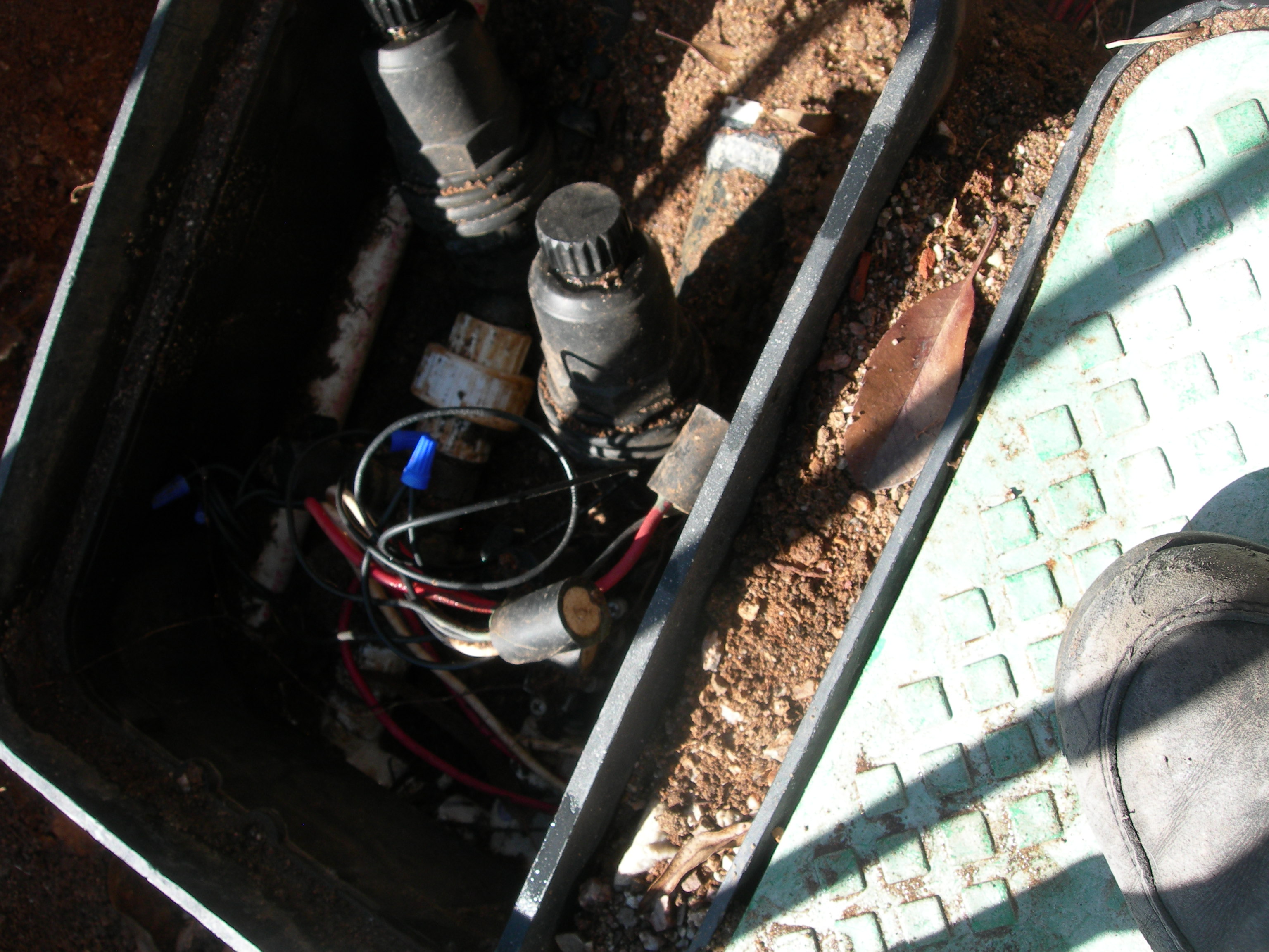
Here is a picture of two of the four valves, which are hard to see under the wires.  The two prominent features are the filters.  The pressure reducers are after the filters and mostly buried.  Part of a white PVC pipe can be seen in the picture.  This is the water source which feeds into the manifold via an elbow that is buried in the lower left of the picture.  There are T’s in the manifold, one for each of the two valves shown.  In the picture, I am standing on another box that houses two more valves, filters, and pressure reducers.  One of the valves in the box my foot is on was stuck, partially “ON” when it was supposed to be off, letting water leak out and water a white rose bush nearby.  The leak had been going on for more than a year.

Two valves and filters

Two valves and filters

I dug up the area on the outlet side of the boxes which also needed attention.  After the relatively easy PVC connections to the manifold and the threading together of the manifold, valves to manifold, filters to valves, pressure reducers to filters, and converters to pressure reducers, there was a complicated set of connections to get the water from valves out to plants that need water when it is hot and dry here in Tucson, which is most of the year.  This valve work was done in October and early November when it was still quite warm.  We have mosquitoes in Tucson now, even in our area outside of town, and with the relatively wet monsoon this summer, lots of these flying bugs made working in the cooler afternoons something less than pleasant.

Below is a picture of some of the “black poly,” that ubiquitous feature of drip irrigation systems.  Black poly pipe is problematic stuff.  It makes it easy to interconnect, but is itself prone to leaking after a few years in the ground.  It doesn’t fail everywhere at once.  Rather it fails one place at a time such that if there is much of it in the yard, there seems to always be a leak somewhere when the valves are on doing their job of watering.  This then requires digging to find the leak and clear a good length of the pipe to replace, cutting out the section that has a leak in it, putting in connectors on the ends of the remaining pipe, and putting in a section of new pipe.

Old black poly pipe connections

Old black poly pipe connections

In this picture you can see part of the white PVC pipe that is the water source for the valves, just visible at the left edge of the photograph.  There is another white PVC pipe shown leading into a brass fitting and vertical copper pipe.  This second PVC pipe comes from the city water meter by the street.  There is a picture later showing it, but between these two PVC pipes is an anti-siphon valve above the ground level.  The anti-siphon valve is there to meet local building code requirements.  It prevents dirty irrigation water from being siphoned into the fresh city water system in the case where city water pressure drops and one of the valves is on.  The anti-siphon valve is also known as a vacuum break.

There are three other white PVC pipes shown.  These go under a brick walkway.  These pipes help prevent having to dig up the walkway.  Because black poly pipe is fairly short-lived, running it under the walkway would lead to much more difficult repairs when leaks occur.  One of the three connections was leaking.  Because they are so far down in the ground, I had thought that while I had the whole mess dug up, I would cut those three PVC pipes and glue PVC fittings and pipes to make the connections to the black poly pipe easier to access.  In the end this seemed like too big of a project for me, and I resolved to just put new adapters on the ends of these pipes and replace all the black poly and elbows, T’s, etc., and be done with it.  In the end, the deepest of the three connections between black poly and PVC still leaked a little.  I dealt with it the best I could.  More on that later.

The wires shown in the photograph are the control wires for the valves.  The red wires are energized one at a time on a schedule controlled by the timer.  The white wire splits up and goes to each valve.  This sometimes is called the “common” because it is in common to each valve, while the red wires are unique, one per valve.  What the white wire really provides is a return pathway for electrons to get to/from the solenoids in the valves.  The solenoids in the valves operate when 24V AC is applied to them.  They are AC solenoids.  AC means alternating current.  Alternating current means that electrons flow toward the solenoid on the red wire during half of the AC cycle, and during the other half of the AC cycle, electrons flow toward the solenoid on the white wire.  Nonetheless, the white wire is called “the return” by convention.  The AC current returns to the timer via the white wire.

Besides what I think is a palm tree root, part of a valve box and lid, and dirt, the rest of what is in the photo are black poly pipes, interconnections between them, and interconnections between black poly pipe and PVC pipes that run under the walkway.  Most of these connections I had replaced when they leaked or when I was replacing the valves before.  It is quite a chore to dig down through dirt by hand, so over time when I have had it partly dug up, I made a point of replacing the dirt with sand.  The sand makes it a lot easier the next time work is needed in this little area of the yard.

The next picture shows a closeup of the three PVC pipes that run under the brick walkway and some of the interconnections mentioned earlier.  This image is prior to the replacement of the valves.  When I got to this point I could see that the three PVC pipes had threaded fittings on the ends that allow converters to be threaded-in to convert from black poly to PVC.  When I saw this, I resolved to simply change the converters and black poly pipe.  It was a little tricky to keep dirt out of the treads, but the Teflon tape probably helped.  I don’t have a good picture of it, but pipe threads like these require Teflon tape to be on the male threads prior to threading them into the female threads.  This seals the connection to make it water tight.  The guy where I bought the parts said to go around only twice or three times maximum, clockwise on the male threads.  If you put on too much of the Teflon tape, the tape can simply get pushed out of the way and leak a little bit.  I have seen this happen.  The irrigation store sells “special” wide Teflon tape that is as wide as the threaded part of most fittings for ease of use.

Closeup of the fittings

Closeup of the fittings

As mentioned, the connection to the lowest PVC pipe still leaked a little after the repair.  I dealt with it, but more on that later.  In this picture you can see the connection to the lowest PVC pipe goes through two elbows and one T.  Later you will see I made this connection a different way to avoid these back-to-back connectors.

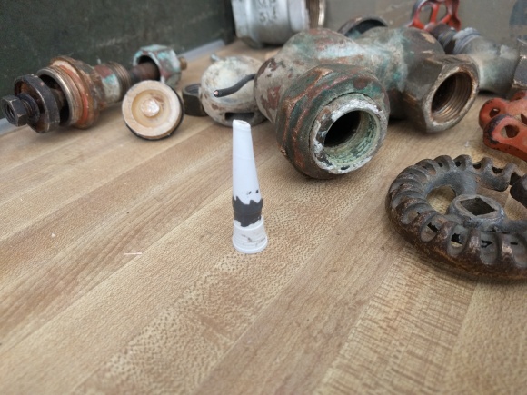
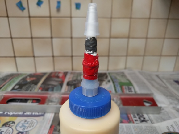
After assessing the situation, I went to an irrigation store and purchased $307 of parts and supplies.  The PVC glue I got is called Red Hot Blue and does not require a primer.  Some PVC glue is two-part: first you put on this really liquidy primer, and then you put on the glue.  The one-step process is simpler, and seems just as effective.  I initially thought I would build the manifold out of PVC pipe and fittings like the old one, but was convinced by the guy at the irrigation store to try something different.

Here is the finished plumbing part of the project.  There were a lot of steps to get to this point that I did not photograph.  It was all pretty stressful.  Doing plumbing that has to withstand city water pressure is serious business, and there is no way to know it will work until after it is done.

Plumbing, irrigation, and electrical connections

Plumbing, irrigation, and electrical connections

There is a lot shown in the above picture.  The manifold is the gray plastic piece to the left-hand side of the photograph.  It is made up of various fittings: an elbow at the bottom left, T’s, straight fittings, and a special T fitting at the top that allows gluing a converter into it for the connection to the PVC pipe from the water source.  The valves are the black things with stainless steel screws in them.  The filters thread into the valves.  The pressure reducers thread into the filters, and the converters to black poly pipe thread into the pressure reducers.  Between each valve and the manifold is a type of union fitting.  A union is a fitting with two parts that come apart.  When the two parts are threaded together, the union is sealed by virtue of a rubber gasket.  Half of the union is threaded into the inlet side of a valve.  It has a gasket to seal to the body of the valve, but the guy at the irrigation store told me to put Teflon tape on that threaded fitting.  I had to go back to the irrigation store to replace a part that was not the right type.  The owner of the store was there that time, and he said the union did not need Teflon tape on it, but that it wouldn’t hurt.  With this manifold system, it is possible to remove one valve, filter, pressure reducer circuit at a time for repairs or replacements.

All of the fittings of the manifold have gaskets.  It went together very easily, and only needed hand tightening.  The whole assembly of the manifold, valves, filters, pressure reducers, and converters for the black poly could be constructed indoors on the kitchen table.  Beyond the gray manifold connections, all other connections required Teflon tape, but only hand tightening.  I glued the PVC converter to the special T fitting of the manifold outside on the front porch.  With that done, I was ready to connect the assembly up to the supply line.

There is a shutoff valve after the anti-siphon valve (not shown) that allows water to be shut off from the irrigation system.  With water pressure off, I cut the supply line with a hacksaw blade with duct tape wrapped on one end as a crude handle.  After cleaning up all the burrs and little bits of PVC, I could glue on a straight connector fitting and the elbow and other short pieces of pipe to make things ready for gluing the manifold to the water supply line.  I put newspaper on the dirt to help keep dirt out of the glue applicator and PVC connections.  After I made all these PVC connections, I realized the elbow needed to be close to perfectly horizontal if the manifold was to be horizontal.  I has just sort of eyeballed the connection of the elbow, and it came out OK.  If I were to do it again, I would be a little more careful to ensure the manifold would be lying flat.

After setting the manifold assembly, I could connect it to the existing black poly and PVC pipes under the walkway, and then connect the wires to the valves’ solenoids.  When I turned on water pressure, there were some little leaks here and there in the manifold and between the manifold and the valves.  I was able to hand tighten the connections and stop the leaks.  The owner of the irrigation store said not to use tools to tighten the connections, that this would lead to problems “down the road.”  Two of the filters leaked when water pressure was on.  The filters come apart and have O-rings to prevent leaks.  I had to go back to the irrigation store to get a couple of new O-rings to fix these leaks.

I bought a roll of landscape fabric at The Home Depot and put pieces of it under the two sets of valves.  this was in an attempt to keep sand from invading under the valve boxes and into and around the valves.  I left the newsprint in place.

The next picture shows a closeup of the black poly connections.  As mentioned earlier, the lowest connection to the PVC pipe that runs under the walkway leaked a little.  Rather than try some complicated PVC repair, I wrapped this connection with part of a bike tire inner tube and clamped it on with two stainless steel pipe clamps from The Home Depot.  You can make these out in the photo.  It still leaks a little when pressure is on that one circuit, but the clamps keep all the water in the pipes from draining out at this low point when water pressure is removed, which is most of the time.  I wish it weren’t like this, but it is.  At this point, it is a project for another day.

Closeup of connections

Closeup of connections

The picture above shows how I tried to simplify some of the black poly pipe connections.  The first in the upper left of the photo and the fourth at the bottom of the photo were simple connections, so no change there.  The second and third were modified to make them a little easier to work on if something does leak.  On the second, I eliminated the complicated elbow-T-elbow stack.  It is a little hard to read in the photo, but from the second pressure reducer the horizontal black poly goes to a T and then on to an elbow before exiting the picture to the right.  The bottom leg of the T goes through a short stretch of pipe to an elbow and pipe that goes to the bottom PVC pipe that goes under the walkway.  The black poly from the third pressure reducer goes horizontally to a T.  One side of that T connects to black poly that exits the photo to the right.  The other side of that first T connects through a short pipe to a T to the left, and one side of that T connects to black poly pipe that goes to a straight connector connected to the existing black pipe that is behind the copper pipe.  The base of this second T connects to one of the PVC pipes under the walkway through a couple of elbows.

After all the connections were made and tested, I set the boxes and tucked the edges of the two pieces of landscape fabric up into them the best I could.  After this, I put dirt – or sandy dirt – part way around the boxes.  The rest of the space I filled with sand.  It’s not perfectly clean sand, but clean enough to be able to dig out easily, and without rocks.

After filling in with sand, I tamped it down and started working on finishing the project.  The river rock area right near the boxes to the top of the next photograph was filled with dirt and in some cases rocks had sunk down and were buried in dirt.  I harvested river rocks for a while, filling about four buckets with them.  Then I smoothed the ground so the transition from the top box to grade (ground level) was gradual.  The boxes sit a little low, and the ground itself needed this smoothing out.  After harvesting river rocks and smoothing out the ground, I put down a layer of landscape fabric to keep the rocks from sinking down into the ground.  There was old landscape fabric in the area, but it was pretty torn up.  You can see some of the old landscape fabric in the upper-right corner of the photo.  Also you can see the anti-siphon valve and the water shutoff valve after the anti-siphon valve.

The finished, landscaped product

The finished, landscaped product

After the landscape fabric was in place, it was time to do the fun job of spreading river rocks to make the whole scene look finished.  I used smaller rocks between the valve boxes, as space allowed.

Birthday Birdhouse Feeder

We have a bird feeder that has been deteriorating over the years, and the ongoing process of patching it up has been a running gag around here.  The feeder is shaped like a little house, reminiscent of a log cabin with two porches and a pitched, gabled roof.  The string that held it up broke first, then as the wood dried out, the long, wire staples connecting the pieces of this little house together started slipping out.  I replaced the string with plastic-sheathed wire, and put screws or nails in as the staples failed.  One of the two boards that comprise the roof had split in two places, and now these separate pieces of wood are linked together with bits of flattened out metal found objects and tiny screws, looking sort of like hinges, but barely holding things together.

I decided to build a new bird feeder modeled after the old one, using redwood fence wood and 3/4 inch garden stakes.  When I started drawing up this plan, I was mistakenly thinking the wood was a 1/2 inch thick, but it is more like 3/4 inch, so the drawing is not exactly to scale.  The side walls will be made out of varying lengths of 3/4 inch garden stake wood, and the end walls under the gables will be clear Plexiglass.

DSCN4629

I started by making the base, which has railings to keep the seed in.  The fence wood is 3-1/2″ wide, so the seven-inch wide base is two pieces of fence wood tied together by the railings.  The length of the base is 11 inches.

DSCN4604

I used 1-1/4 inch screws on the railings to keep the screws from going all the way through the wood.  I had to adjust the length of the end pieces, so I sanded them a little to fit.

DSCN4606

After making the base, I built the “log” walls out of six inch and eight inch pieces of redwood stakes.  I pre-drilled the clearance holes, staggering them, and leaving room for slots where the Plexiglass would go.

DSCN4608

I used 1-1/2 inch screws, which are a bit longer than the thickness of two pieces of wood, the 3/4″ wood actually being more like 11/16″ thick.  I ran the risk of the screws going all the way through two boards and hitting the screw head two layers down, but somehow it didn’t seem to matter, probably because I don’t drill very straight.   As usual, I would drill one pilot hole and attach the first screw before drilling a second pilot hole for the second screw.

DSCN4609

After the walls were built, it was time to cut the slots for the Plexiglass.  I used a saw in a miter box, which kept the saw straight up and down.  Still, this was an unforgiving process, requiring two cuts to be made, and then breaking out the little wall between the cuts.  It was hit or miss, but somehow I got it done.

DSCN4610

After the walls were made, it was time to attach them to the base.  First I marked the base where the walls would go.  Since the 1-1/2 inch screws poked through the wood a little, I could press the screw points into the railings of the base to register where they would go for the next step of attaching the walls.  I drilled the clearance holes from the top of the base to get them as centered in the rails as possible.  I used 2-1/2 inch long, #8 screws, so the clearance holes were bigger than the ones for the #6 screws used elsewhere.  I would have used #6 screws for the longer screws, but #8 was all I could find at the store.

DSCN4612

This was a tricky part, because the walls needed to be vertical when drilling the pilot holes for the 2-1/2 inch screws.  The pencil marks and registration afforded by the screw points in the side rails of the base helped locate the walls.  I did the best I could with getting the wall straight up and down.

DSCN4613

In this picture, the screws are going in to attach the base to the walls:

DSCN4614

I decided to put braces between the walls for later, when the gables are attached.  All the weight of the feeder transmits through the gables, so it is important that they are connected into the structure well.

Here is the feeder with the walls up and the braces in place:

DSCN4616

I bought a piece of Plexiglass at a local glass store, and I measured and cut it to fit.  Plexiglass is similar to glass, but cutting it requires scoring a line on the surface over and over with some kind of blade and snapping it.  I used a linoleum-knife type of tool to score the Plexiglass, and snapped it by holding one side down on a box with the scored line along the edge of the box, then quickly pushing down on the overhanging side.  In some cases it didn’t break cleanly along the scored line, but I was able to snap off little pieces by grabbing them with a pair of pliers and breaking them off that way.

With the Plexiglass cut, it was time to make the gable ends.  I had planned to use the miter box to cut the 45 degree angles this step would require, but the 3-1/2″ board was too big for the miter box’s clamps, so I used the rafter square to mark the 45’s by lining-up the bottom of the board with equal numbers on the two halves of the square, 4-7/8″ in the picture below.  I marked the wood and cut the upper right hand corner off, then measured the distance for the base of the triangular gable, repeating the process above to make the second 45 degree angle cut.  One more measuring and another 45 degree cut later, and I had the two gable ends.

DSCN4632

I thought the braces were too far away from the Plexiglass to prevent the birds from being able to climb behind the gable and into the space where the seed goes, so I decided to move the gables in a little.  This required a fair amount of care when drilling, or else the pilot holes would miss the brace pieces.  It also was not too easy to keep the gable from sliding when trying to drill through the clearance hole in the gable and into the brace.  So I used the smallest drill bit to get a pilot hole started in the brace, then once it was drilled with a small drill, increased the bit size to 5/64″ for the #6 screw pilot hole.

DSCN4617

Even using 1-1/2 inch screws, the brace and gable were not connected that well together, so I decided to remove the gable and brace pieces and put in another screw, this one straight through the brace and into the gable to secure the two together better.

While I had the braces and gables off, I put in small brass screws to hold the Plexiglass into place.  This will keep birds from going under the Plexiglass and getting trapped in where the seed goes.

DSCN4618

Here is a picture of a 1-1/2 inch screw going in to strengthen the connection between brace piece and gable end.  Note the slotted screw near the apex of the gable.  This is where one of the wires will attach to hold the bird feeder up.

DSCN4619

With the gables attached, it was time to make the roof.  I had decided on nine inches for the length of the roof, but found three boards I had from before that were about 9-1/4 inches, and decided to make the roof 9-1/4″.  One more cut and I had all the pieces I needed for the roof.

DSCN4600

I used big hinges to connect two board together to make one half of the roof.

DSCN4620

And I used smaller hinges to connect the roof pieces to the ridge beam – made from the end of a garden stake.

DSCN4621

I had to be careful about the placement of the smaller hinges in order to allow space for the wires that had to go through the ridge beam and tie to the slotted screws in the gables.  I filed little flat areas on the beam to make places for starting to drill the holes for the wires.  I did this very gradually, first using the smallest drill bit, and working up to 1/4″ holes.

DSCN4622

I straightened two pieces of plastic coated wire about 13″ long, stripped back the coating, and attached them to the slotted screws.  Then I was ready to thread the wires through the roof holes and attach them to a hanger I’d made.

DSCN4624

I made the hanger out of some really heavy steel wire I found in the garage and attached the green plastic coated wires to the hanger.  Here is the finished bird feeder suspended from a cabinet pull.

DSCN4626

And here is the reverse angle.

DSCN4625

Here is the feeder ready for use.  I left the pointy end of the garden stake as part of the ridge beam.  It’s a nice touch I think, and reminds me of something that might be done when building a barn, to have a place to attach a pulley for raising hay bales into the loft, or a block and tackle for pulling an engine out of an old pickup truck.  The smaller hinges function very well when putting seed into the feeder.  With the old feeder, the whole roof had to be lifted up.  The hinges make it a lot less cumbersome.

DSCN4627

St. Valentine’s Table

When the weather is not too cold or too hot, it’s nice to sit outside in the evenings.  So we made a seating area near the citrus trees, accessible from the steps we built last spring.  There is a chiminea for a small fire in case it is a little cold.  Here is the area, covered in snow, on February 20th.

Seating Area

To have somewhere to set drinks or snacks, I decided to make a little table out of redwood, a material that holds up well outside in the desert.  I used inexpensive pieces, 5.5″ fence wood, 3.5″ fence wood, and 3/4″ x 3/4″ redwood stakes.

I did not draw up detailed plans, but decided on having  the table be square and have a shelf.  The overall height would be 18″ with the shelf at 6″.  The shelf would be the width of four 3.5″ boards, or 14″, and the top would be the width of five 3.5″ boards, or 17.5″.  These are approximate dimensions because fence boards are notoriously irregular in all dimensions.  That is okay; it just requires making adjustments to match the dimensions of the boards on hand at the time.

Here is my plan on paper.

Drawing

Pretty sad, I know, but I can use the lower drawing to illustrate something I don’t have a good photo of later in the blog.  I will not go into it now, but it has to do with attaching the table top to the legs that support the top.

The weekend before Valentine’s Day I had the materials together and started the project.  I cut four 5.5″ boards to make the 14″ square base, and I cut four 3/4″ stakes for the legs that extend from the base to the table top.  I drilled two clearance holes in one 5.5″ base piece and one pilot hole in one 3/4″ leg piece, lining up the leg with the edges of the base piece when drilling the pilot hole through one of the clearance holes.

Base piece and leg

After attaching these two pieces together with the first screw, I used a steel square to make the base at a right angle with the leg before drilling the pilot hole for the second screw.

Squaring base to leg

I followed the same method to add the second leg to this one base piece, and repeated the same steps to make another base piece with two legs.  Eventually I put three screws instead of two in an effort to take some of the warp out of the 5.5″ redwood base pieces.  The wood I got was actually wet when I bought it, and it had warped.  It would have been better to look for wood that was dry and not warped, but it still works, and adds to the rustic nature of the piece.

Squaring the second leg

Then it was time to connect the two pieces with legs together to make the square base.  This involved working with the pieces tilted, but eventually I could connect another of the 5.5″ boards and square things up before drilling the pilot hole for the second screw.

Adding a sdie piece squarely Side squared up

I continued on, attaching the other piece with two legs to the angled piece, drilling both clearance holes in the side piece, then the pilot holes one at a time.

DSCN4556

This kept things quite square, but you can see how little errors could start adding up.

Squaring before drilling second pilot hole

All that was left to complete the base was to attach the other side piece.  Here I squared things up the best I could.

Finishing the base

Time was running short and daylight was waning, so I didn’t get pictures of adding the shelf.  The shelf was made from four 3.5″ redwood boards that were approximately 14″ long.  I had to notch out two of the boards to make room for the legs.  I attached the shelf boards with finishing nails.  If these eventually get loose, I can attach them with screws, but nails work fine for now.

I used clamps to glue the five 17.5″ long 3.5″ boards together for the top.  I attached 3/4″ pieces to make a frame around the top’s perimeter so I could take it out of the clamp without letting the glue dry.

Clamping the top

This is where you might refer back to the drawing as a view of the underside of the top, showing where the legs attach.

Legs and underside of top

With the top lying top down, I set the base leg-side down on the top.  I tried measuring to position the legs, but eventually found that adjusting their locations until it looked right was easier and better.  I wanted them to sit neutrally, without any spring in the legs, and to look centered.  Once I had them where I wanted them, I marked all four corners of each leg in pencil on the underside of the top.  I marked one leg and the top as a key to remember which leg went where.

I removed the base and drew an X with a straight edge to locate the center of where each leg’s corners were marked.  Then I drilled four holes, one hole in the center of each X, from the bottom.  This created pilot holes on the top side of the top for a later step.

After the four holes were drilled, I put glue at the four locations where the legs would sit.  Then I replaced the base piece, with the legs back in their original marked locations, and put a weight on the underside of the shelf to glue the legs down to the top.

Gluing legs to top

Once the glue was set, the table construction was done except for permanently attaching the top to the legs.  This process started by drilling long pilot holes into the centers of the legs from the top, using the pilot holes from the previous step as guides.  I used four longer screws, 2.5″ ones, to attach the top to the legs.

Top showing pilot holes

To finish the piece, I painted it with a good quality natural-wood colored exterior stain.

Finished piece

Bees and Owls

I had made a couple of nest boxes for western screech owls.  The first of these produced two fledglings in its second year.  Here is a picture of the two, shortly after leaving the nest.  A full grown western screech owl is not much bigger than these juveniles.


When cleaning out the first owl nest box around the end of October that year, the box fell apart, and a second owl box had to be made.  Here is a picture of that second box, in the same location as the first, about 12 feet above the ground in a large mesquite tree.

This second owl box went up in November 2010, and had visitors over the winter and spring, but no takers in terms of nesting in spring 2011.  There was considerable interest in the box by spring 2012, and I was sure a male screech owl would attract a mate to it.  That might have happened, had it not been for bees moving in – in April or May of 2012.

As with the first, the second owl box was starting to crack that spring.  The weight of bees and honey didn’t help, and it was in rough shape by the end of the summer.  In October 2012 I had a live-bee-removal service come out and take the box and bees away one evening.

The bee man came by in an old Ford pickup truck with the driver’s side door missing, and got the now bee box down.  One side of the box was split almost wide open, honeycomb filling all the gaps; the 3″ opening in the front was solid propolis, some mysterious product bees make.  The bee man used a smoker with weeds as the fuel, and put in ammonium nitrate fertilizer which decomposes to nitrous oxide to keep the bees from being too agitated.  Except for one bee that got in his ear, he seemed to get them all.  But the next day I saw a handful of bees buzzing around the area where the bee box had been.

Oh well.  Time to make a new owl box!

It was not easy to get the second bee box down, because the stainless steel screw in the mesquite tree was frozen in place.  Because of this, I decided to make it so the new box could at least in theory be brought down without any tools.  Also, I was motivated to make a box that would last longer than two years and to use relatively inexpensive wood.

I decided on 3.5″ X 11/16″ redwood fence wood with 5/8″ X 1  3/8″ redwood boards to bind them together .  We have some adjustable clamps and exterior wood glue.  Here is the basic process:

After cutting all of the pieces, it just took glue, screws, and drilling clearance and pilot holes, to make the individual boards.


There are websites devoted to such things as screech owl nest boxes, and I used the same basic design I had before.  The back board is 22″, the sides and front are 16″.  I glued three pieces of the fencing together, making the width of each of these boards 10.5″.  I used four boards for the top so there would be overhang.  The bottom piece fits inside, between the sides, so has to be cut to fit.  It is better if the bottom piece is a little short.  Gaps in the bottom will allow drainage should water find its way inside.  Drainage holes are also drilled in the bottom for the same purpose.
I did a dry fit with the bottom, sides and front to line up those pieces before attaching them.  Here are the bottom and one side:

Somewhere in here I decided to use a piece of cardboard to have an even surface to work from.  Here is the bottom with both sides:

Once I had everything line up just right, I put on glue:

I quickly attached the front with four screws to locate and hold things together.  This took a little doing.  I predrilled the clearance holes in the front for the screws.  Then I put on the glue and set the front on the sides and drilled one pilot hole in the location for one of the four screws.  The pilot hole is small, 1/16″ for a #6 wood screw in soft wood.  One at a time I put in the four screws shown below, realigning things before drilling each pilot hole.

After this, I quickly drilled all the pilot holes and put in all the screws before the glue set up.

After attaching the front to the sides, I attached the bottom.  I had to use two-and-a-half inch screws because of the thickness of wood.  I didn’t use glue.

After attaching the bottom, it was time to attach the back, the 22″ board.  I lined up the sides to the back board, and put a temporary cross piece to “remember” where the bottom was when things were lined up.  After doing that, I flipped over the part that was already assembled.

Then it was ready for glue and attaching the back.  You can see the temporary piece that helped in lining up the back to front-side-bottom assembly.

Here is the box, almost finished, with the top set in place.  Rather than have hinges for the top, I made it so the top interlocks under a cross piece attached to the back.  In the front I put screw eyes and used wire to hold the top down.  I made a handle out of wire to help in carrying the box.

I got wood shavings at the pet store.  The owls like a few inches of shavings in the bottom of the box.

I carried the box while climbing the tree, setting it different places on the way up so I could use two hands to climb.  I had made a slot in the bottom of the back board to make it easy to slip over the stainless steel screw left from the earlier owl boxes.  I put a bracket on the back board to reinforce the slot.

At the top, I used wire to hold the box to a branch, and longer wire to pull the box to vertical.  It is important that the box is not tilted.  The owls want it to be vertical.

Here is the new box, ready for owls to find it.

Rain in the Desert

It was the Fourth of July and one of those odd days in the summer in Tucson when it does not get hot.  The high was in the 80’s, and it was quite a bit cooler once the heavy clouds and rain moved in.  We got a late start, but went to Sabino Canyon for a hike.  Mainly the trails were level, and it was fun exploring a short way on the Phoneline Trail, the dam area, and the mostly dry creek bed of Sabino Creek.

Here are the mountains, and clouds rolling in at about 1:00 p.m. as we walked along the trail between the parking lot and the Phoneline Trail.  The actual phone line seems to have been a single-wire telegraph line that went up into the Santa Catalina Mountains from Tucson.  You can actually find stretches of the steel wire along the trail in certain places.

Here is an odd little bug that was on the Phoneline Trail.  It started to look more stormy, so we headed back down to check out the dam area and went up above the dam, eventually connecting with Upper Sabino Road.  There was almost nobody on the trams that ferry people up and down this road that is inaccessible to private vehicles.

Here is a look back up the road as we were leaving.  Sabino Canyon is to the right.  The road goes up about three miles from this point.  The clouds were looking ominous.

It’s hard to tell, but the rain was almost on us at this point, moving towards us and only a few hundred yards away.  By the time we got to the end of this road we were getting soaked!

One last look back before the rain started.

Wrought Iron Finished

It’s a bright sunny morning that portends of rain this first or second full day of summer.  The wrought iron color turned out well, don’t you think?  I reserved the black plastic caps over the ends of the wrought iron and replaced some missing ones.  They make a nice detail.  I’ve been noticing wrought iron around town and old places.  Unpainted is the way to go, I think, with the real stuff.

The grapes are ripening in the background of this shot.  To keep the birds off I staple paper lunch bags individually over the bunches.  The bottom corners of the bags are snipped off to allow air to circulate.  Mold can be a problem.  Thompson seedless are on the left, Flame seedless in the middle, and Ruby seedless on the right.  They ripen in about that same order, left to right, not because of position, but because of species.  Thompson and Flame are about the same, and usually ripen before the rains.  Ruby seedless ripen later, and because of the rain, are hard to keep covered in bags and to fully ripen.  There are also large scarey flying beetles that appear and get into them (the Ruby grapes), startling the viniculturalist checking the bunches.  The Ruby aren’t quite as good as Flame and Thompson anyway, but no sour grapes.  They just don’t work out quite as well for me, and the skins are a bit tougher than the earlier two varieties.  They are good in their own special way.  Birds love them all.

This is some wrought iron at San Xavier mission outside of Tucson, who knows how old.

And here are the bars over the windows of the garage.  After the fact I noticed that the horizontal pieces are hollow and have caps over the ends.  The caps do help with the illusion of the wrought iron being solid, but I may carefully pry them out and replace with new black ones from Ace Hardware.  The vertical pieces are solid, and these three sections are quite heavy because of it.